rEVERSE eNGINEERING PROJECT
It all started with the curiosity to explore what sort of processes and testing goes behind the scenes while designing a system. Upon exploring and researching in depth about various test procedures I finally started designing the first component of the mega assembly which consisted of 100 different components.Hybrid modeling is a commonly used term when NURBS and parametric modeling are implemented together. Using a combination of geometric and freeform surfaces can provide a powerful method of 3D modeling. Areas of freeform data can be combined with exact geometric surfaces to create a hybrid model. A typical example of this would be the reverse engineering of a cylinder head, which includes freeform cast features, such as water jackets and high-tolerance machined areas.

SEE HOW IT WORKS.....

dESIGN AND working
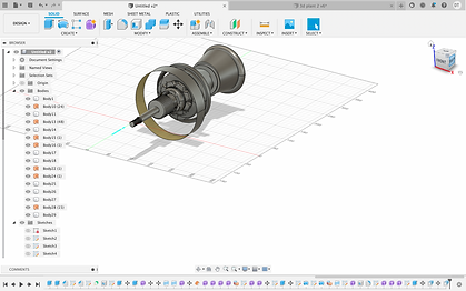
STAGE 1- Designing the compressor and the turbine
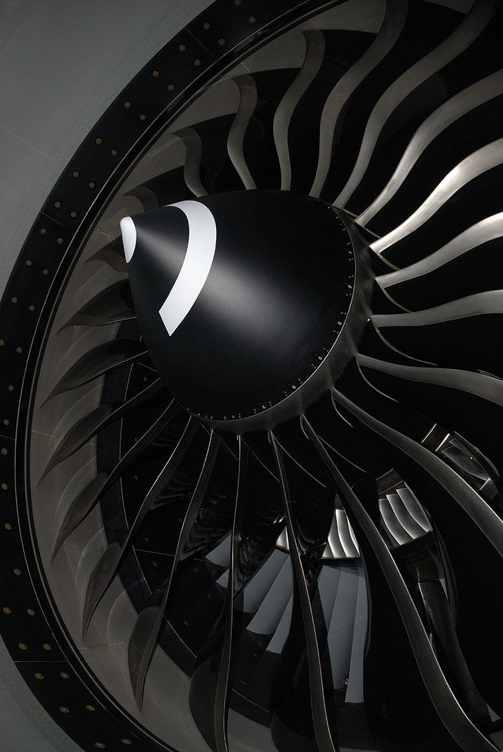
The key component that makes a compressor centrifugal is the centrifugal impeller which contains a rotating set of blades. In a centrifugal compressor, the airflow goes perpendicular to the axis of rotation. When the air passes through the rotating impeller it experiences a centrifugal force. Air is pushed toward the center and this radial movement of air results in a pressure rise and the generation of kinetic energy. gas turbine engine compressors provide the compression part of the gas turbine engine thermodynamic cycle. There are three basic categories of gas turbine engine compressors: axial compressors, centrifugal compressors and mixed-flow compressors. A fourth, unusual, type is the free-piston gas generator, which combines the functions of a compressor and combustion chamber in one unit. Designing the compressor was a bit challenging with all the curves and the extrusions. Started the design with the axial rod and extruded the high temp and low temp compressors using the mesh tool. The turbine motor was the main part of the stage 1 design as it required the highest amount of precision due to its aerodynamic design.


STAGE 2 - WIRING AND PCB DESIGN
Modelling the wires and the compressor tubes was the most challenging part of the design as it required highest precision and time.The satisfactory performance of any modern aircraft depends to a great degree on the continuing reliability of electrical systems and subsystems. Improperly or carelessly installed or maintained wiring can be a source of both immediate and potential danger. The continued proper performance of electrical systems depends upon the knowledge and technique of the mechanic who installs, inspects, and maintains the electrical wire and cable of the electrical systems.
The term “cable,” as used in aircraft electrical installations, includes the following:
-
Multiconductor cable—two or more separately insulated conductors in the same jacket.
-
Twisted pair—two or more separately insulated conductors twisted together.
-
Shielded cable—one or more insulated conductors, covered with a metallic braided shield.
-
Radio frequency cable—a single, insulated center conductor with a metallic braided outer conductor. The concentricity of the center conductor and the outer conductor is carefully controlled during manufacture to ensure that they are coaxial.


ASME wiring standards
According to the ASME( American Society of mechanical engineers), all the wiring and PCB designs have to meet a certain requirement to be approved.ASME standards – also known as ASME Boiler & Pressure Vessel Code or BPVC – is the code that regulates the design, development and construction of boilers and pressure vessels utilized in a variety of industries. The table given shows all the wires of accepted requirements .

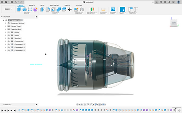
DESIGNING THE FAN BLADE, SPINNER AND OUTER BODY
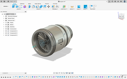
Designing the fan blade and the turbine and welding it to the engine was the toughest part and took the most time. Used features like symmetry, splines, extrusions and revolve.
The core is the more traditional “jet engine”, but instead of strictly providing thrust by pushing air out of the exhaust section, it also turns the fan at the front of the engine.
This is much more efficient than a pure “straight tube” turbojet engine. It is more efficient to accelerate a large air mass by a small amount than a small air mass by a large amount. Thus most of the thrust created by a jet engine is created by the high-diameter fan, not by the core.
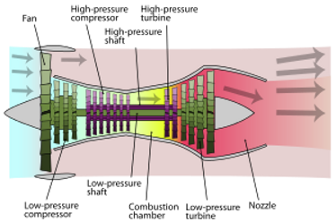
Sectional view of a jet engine

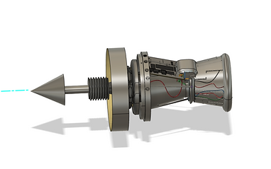
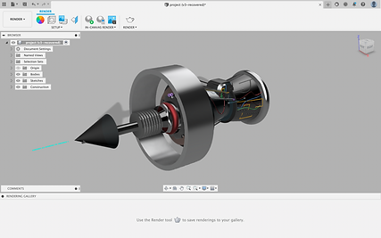
FINAL DESIGN
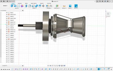
The final assembly consisted of almost 100 components and to weld them together using the modified tool was challenging as I had to weld them precisely looking at their orientation from all different positions.
List of different sections-
1. Intake
2. Low-pressure compression
3. High-pressure compression
4. Combustion
5. Exhaust
6. Hot section
7. Turbines Low and High pressure
8. Combustion chambers
9. Cold section
10. Air inlet
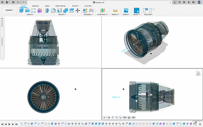


WORKING
Making the turbofan rotate was one cool thing I wanted to do but as we say cooler the things sound harder they are to execute, it took me 2 hours to figure out how to fix the fan on the axis and rotate it about the right axis and control the number of revolutions. The first video on the top left shows how i built the whole assembly using various tools and the one on the top right shows the rotation of the turbo fan at 85rpm per minute.
TESTING AND RESULTS
1. ZEBRA ANALYSIS
The zebra analysis tool projects stripes onto a surface so that you can inspect the continuity between surfaces.
Surface continuity is a measure of how smoothly two surfaces flow into each other. A car hood, for example, can be composed of multiple small surfaces that appear to be one because of the smoothness of the surface continuity. Zebra analysis can also identify flaws in what should be a fair surface in a ship hull, an issue that can increase drag and have structural consequences in some cases.
IGO position- As we can see that the surface edges collocate and we can say that there are no disruptions in the design.
G1 tangency- As seen in the test result that there are no curves in the zebra lines, this indicates that all the curves are perfectly aligned with the tangent lines.

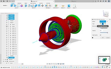
2.CURVATURE MAP ANALYSIS
The Curvature Map Analysis command displays a color gradient on a body to help you analyze areas of high and low surface curvature in Fusion 360.
What do the results mean?
-
Gaussian: Displays a gradient as the product of curvature in the U direction and curvature in the V direction.
-
Red, Orange, Yellow: The region has positive curvature.
-
Green: Region is a flat surface in one or both directions.
-
Blue, Indigo, Violet: Region has negative curvature.
-
-
Principal Minimum: Displays a gradient that highlights the areas with the lowest curvature.
-
Green: Region meets Maximum Limit threshold.
-
Red: Region exceeds Maximum Limit threshold.
-
-
Principal Maximum: Displays a gradient that highlights the areas with the highest curvature.
-
Green: Region meets Minimum Limit threshold.
-
Red: Region exceeds Minimum Limit threshold.
-
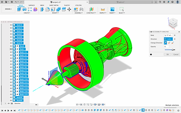
3. ACCESSIBILITY ANALYSIS
Accessibility Analysis determines if an area of the model can be accessed through a select plane's view. The model is colorized based on the areas accessible through the selected plane. This can be useful to determine undercuts and inaccessible areas of the model.
4. MINIMUM RADIUS ANALYSIS
A tool that shows areas of a model that are at or below the minimum radius is useful for manufacturing purposes to see what areas of the model can't be machined with a certain cutter radius. Minimum Radius Analysis highlights areas of high and low curvature on the model and is helpful while identifying the minimum tool radius that is necessary to create these parts in subtractive manufacturing..

5. MATERIALS AND SAFETY FACTOR
Choosing the right material is of utmost importance while building a product, there are several tests that need to be done while choosing a material.
Some important tests to be performed while choosing a material are-
1. NDT or non-destructive testing
2. Tensile test
3. Composition test


TOOLS USED
